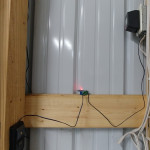
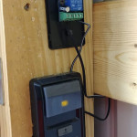
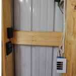
I was looking at garage door openers for my new pole barn and kept seeing they wanted like $100 for the wifi modules for all these units…. now im sure they all are a little smarter and more sophisticated like logging door openings and giving and open or close status.. if you want all that probably best off buying one of their units, if you just wanna be able to open it from anywhere or without a garage clicker in your car or with alexa or google, this will get er done.
my garage door has one of the new fangled opener buttons that has like 3 buttons “learn, light, open” so it’s not just shorting the two wires out like some of the older ones.. if you have one of the older ones you can just put this in parallel to your current button and it will function without any soldering.
firstly here is a list of items needed to complete the project.
- soldering iron and solder
- small 20-24 gauge wire
- phillips head screwdriver
- momentary wifi switch module this is what i bought.
- multimeter
- 12v power supply
- project box that will fit the wifi module
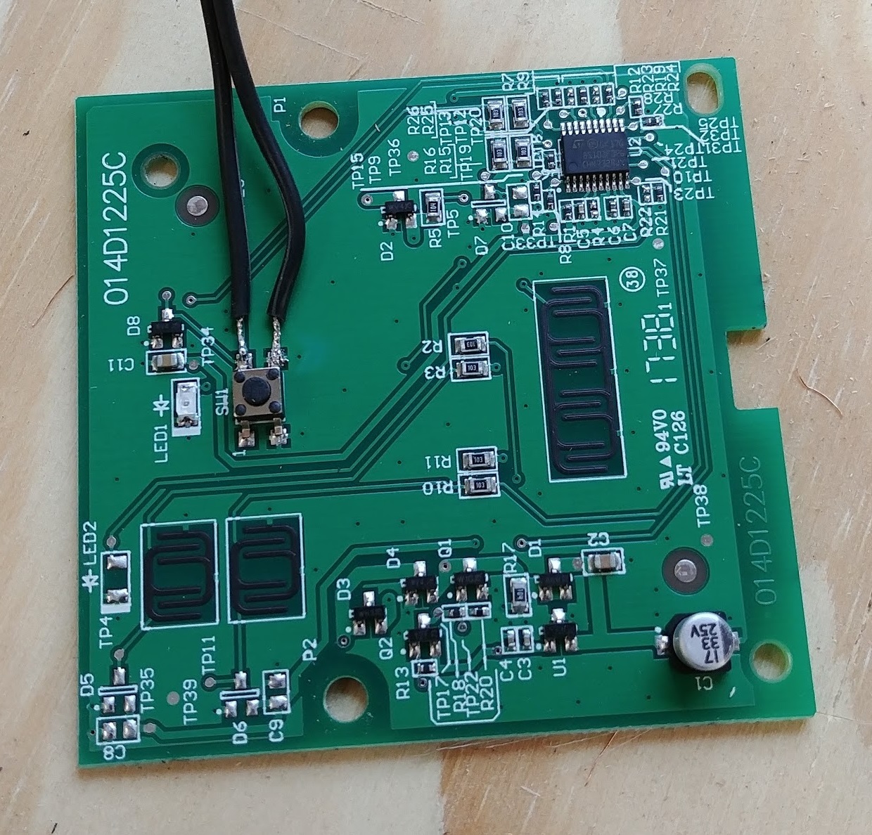
to start first take your button off the wall and remove the wires from the back by loosening the two screws holding them to the pcb, and go ahead and take those screws the rest of the way out, on mine they were the only thing holding the pcb in besides friction, so now we just need to pop the pcb out of the plastic housing gently.
once the pcb is out of the housing go ahead and look for the button that is pressed when you hit the “open button” usually its gonna be an smb mounted tactile switch, now you are going to want to use a multimeter and see which terminals are normally open and normally closed you’re gonna want to go with two of them that are normally open with infinite resistance, after the pair you want to use have been identified you need to solder the 24g leads to the board, the other end of the leads will go into the NO and COM terminals on the wifi switch (normally open and common).
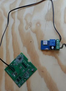
after that is hooked up and the wire is ran to your terminals on the wifi switch, were gonna hook up our 12v power to the wifi switch, simply put positive with positive and negative with negative, if your leads on the 12v psu aren’t clearly enough marked you can use the multimeter to check, put it on DC voltage setting and touch the two 12v leads while its powered on, if it has a -12.0
instead of 12.0 you switch the leads around and check, what ever the red multimeter lead is on is positive and black is negative when you get a positive reading.finally connect your wifi module to the EWELINKS app, register your account, then hold the button on the wifi switch for 5 seconds it will change its flashing of the led and you are ready to connect it, once its connected press the button on your phone and bam! should be working! now that its verified its working go ahead and put the wifi switch into the project box and route your wires however you want just make sure you get them back in the right hole.

